Tuesday 10 March 2015

CIM Oct-2015, April - 2015, April - 2014 , Oct-2014 Question Papers

CIM  Oct  - 2015 Question Paper
887
Part A

1. List out any four benefits of CAD.
2. Mention any four CAD software packages.
3. What is scaling?
4. Expand IGES and PHIGS.
5. What is group technology?
6. What are the types of CAPP?
7. Define capacity planning.
8. What is rapid prototyping?
9. Define numerical control.
10. What is adaptive control system?
11. What is the function of transducers?
12. What are the types of feed drives?
13. What is NC part programming?
14. What is meant by tool offset?
15. What is difference between G00 and G01?
16. What is meant by peck drilling?
17. What are the components of FMS?
18. What is virtual machining?
19. Expand ASRS.
20. Define robot.

Part B
21. A. i. Explain various activities of CAD. - 7
           ii. Distinguish between boundary representation and constructive solid geometry. - 5
Or
     B. i. Explain with a neat sketch about the CIM wheel. - 8
          ii. List out the advantages of finite element analysis. - 4

22. A. i. Explain OPITZ classification system. - 8
           ii. What are the advantages of CAPP? - 4
Or
     B. i. Explain just-in-time manufacturing philosophy. - 6
          ii. Explain 3D printing.

23. A. i. Distinguish between NC and CNC. - 4
           ii. Explain the construction and working  of coordinate measuring machines. - 8
Or
     B. i. Explain the construction and working principle of  machining centres. - 8
         ii. Explain working principle of stepper motor. - 4

24. A. i. With a neat sketch explain NC coordinate system. - 4
           ii. Write a sample part programme for producing component using CNC lathe - 8
Or
     B.  i. Explain types of motion control. - 6
           ii. Explain the use of macros with a simple CNC programme. - 6

25. A.  With a neat sketch explain various types of  FMS layouts. - 12
Or
      B. i. Explain working principle of AGV. - 8
           ii. What are the robot configurations - 4


CIM  April  - 2015Question Paper
567
April  -2015
Part A
1. What is CAD?
2. What is concatenation?
3. What is the need of graphics standard?
4. What is graphic workstation?
5. Define CAM.
6. List the advantages of CAP.
7. What is capacity planning?
8. What is sequential engineering?
9. What is DNC?
10. List the features of CNC machines.
11. What is the purpose of CMM?
12. What are transducers?
13. Mention the methods of part programming.
14. What is NC dimensioning?
15. What is canned cycle?
16. What is circular interpolation?
17. What is FMS?
18. What is virtual machining?
19. List the benefits of AGV.
20. Mention the methods of robot programming.

Part B

21. A i. Explain the the Shigley's design process.
             ii. Explain the 2D transformations with example.
Or
      B. i. Explain the solid modelling techniques.
           ii. Explain the IGES standard.

22. A. i. What is group technology? Explain the methods of grouping parts into part family.
          ii. Write short notes on
                1. Manufacturing Resource Planning 2. Shop floor control.
Or
      B. i. Explain the product development cycle.
           ii. Explain the laser sintering process of RPT. Mention its advantages and disadvantages.

23. A. i. Explain the working principle of CNC system.
           ii. Explain the working of ATC.
Or
     B. i. Explain the construction and working of CNC machining centre.
          ii. What is a feedback device? Explain the principle of rotary transducer.

24. A. i. Explain about the tool materials and tool inserts of CNC machines.
           ii. Describe about conversational programming. Explain the concept of tool compensation.
Or
     B. i. Write the procedure to create a CNC program. With example explain linear interpolation.
         ii. Write a part program to explain the mirroring operation in CNC machining centre.

25. A. i. Explain about the components of FMS.
           ii. Explain the FMS layouts.
Or.
     B. i. Explain the working principle of of AGV.
          ii. Explain the configurations of robot.

%%%%%%%%%%%%%%%%%%%%%%%%%%%%%%%%%%%%%%%%%%%%%%%


 CIM  April  - 2014 Question Paper
234
April  -2014
Part A
Image result for robot application
1. List the benefits of CIM.
2. What is CAD?
3. What is graphics standard?
4. What is 3D rotation?
5. List the benefits of CAM.
6. What is GT?
7. What is Master production schedule?
8. What is sequential engineering?
9. Define DNC?
10. Mention the advantages of of CNC machines.
11. What is ATC?
12. What is an encoder?
13. What is conversational programming?
14. What is a datum point?
15. What is macro?
16. Mention the syntax for threading cycle.
17. What is FMS?
18. What is virtual machining?
19. Define robot.
20. What is AGV?

Part B

21.  A. i. Explain the activities of CIM wheel. - 6
           ii. Explain the guidelines of design for manufacture and assembly. - 6
Or
      B. i. Explain the activities of CAD in Shigley's  design process. - 6
           ii. Explain the 3D rotation and 3D translation. - 6

22.  A. i. Explain the generative type CAPP. - 6
           ii. Explain the MRP - I. - 6
Or
      B. i. Explain the code system. - 4
           ii. What is RPT? Explain the stereo lithography method. - 8

23.  A. i. Explain the working principle of CNC system. - 6
           ii. Explain about the the design considerations of NC machine tools. - 6
Or
      B. i.. Explain the working principle of EDM die sinking machine. - 6
           ii. Explain about the ATC. - 6

24.  A. i. Explain the NC dimensioning methods with example. - 6
           ii. Write a part program for thread cutting operation in a CNC lathe. - 6
Or
      B. i. Write a part program for pocketing in a CNC milling machine. - 6
           ii. Explain about the tool offsets and tool compensation . - 6

25.  A. i. Explain about the FMS components. - 6
           ii. Explain the intelligent manufacturing system. - 6
Or
      B. i. Explain the working principle of AGV. - 6
           ii. Explain any two industrial applications of robot. - 6
%%%%%%%%%%%%%%%%%%%%%%%%%%%%%%%%%%%%%%%%%%%%%
887
Oct-2014 
Part A
1.       What is concept of CIM?
2.       What is graphic workstation?
3.       What are the techniques of geometric modeling?
4.       Define graphic standard.
5.       What are the types of coding structure?
6.       What is master production schedule?
7.       Define concurrent engineering?
8.       List out any two materials used in rapid prototyping.
9.       What are the components of NC system?
10.   List out any four advantages of CNC machines.
11.   State any two requirements of good slide ways.
12.   What is the function of encoder?
13.   List out any two formats used in NC part programming.
14.   What is point to point motion control?
15.   What are the functions of M02 and M06?
16.   What is macro?
17.   What are the benefits of FMS?
18.   List out any two types of AGV.
19.   List out any two robotic sensors.
20.   What is intelligent manufacturing system?

Part B
21. A)  i) What are the benefits of CIM? -  4
          ii) Explain the implementation of GKS in CAD workstation? - 8
(OR)
      B)   i) What is transformation? Explain the translation. - 4
         ii) Explain constructive solid geometry. - 8          

22. A)  i) What are the benefits of CAM?  - 3
           ii) Explain with neat sketch the variant type CAPP? - 9
(OR)
     B) i) Explain product development cycle. - 8
        ii) Describe enterprises resource planning. - 4

23. A) i) Explain  working principle of CNC system. - 6
          ii) With neat sketch explain the working of re-circulating ball screw. -6
(OR)
     B) i) Explain the  working principle of wire EDM machine. - 6
ii) Explain the working of DC servomotor.  - 6

24. A) i) Explain APT programming . - 8
           ii) Explain the peck drilling cycle. - 4
(OR)
     B) i) Explain machine zero and work zero. - 4
        ii) Write a sample part-programme for milling. -8

25. A) i) Explain flexible manufacturing cell.   - 6
           ii) Describe basic robot motion. - 6
(OR)
    B) i) What are the benefits of AGV?  - 4
       ii) Explain industrial applications of robot. - 8
Monday 2 March 2015

Robot anatomy and related attributes


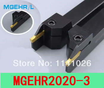
http://www.shop-apt.co.uk/external-grooving-tools-for-mgmn-inserts/mgehr-2020-3-external-groove-and-turn-tool-20x20mm-shank-3mm-wide-18mm-max-depth.html


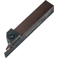
MGEHR 2020-3 External Groove and Turn Tool 20x20mm Shank 3mm Wide 18mm Max Depth

MGEHR 2020-3 External Groove and Turn Tool 20x20mm Shank 3mm Wide 18mm Max Depth
Zoom  Zoom
Our Price:  £30.80
List Price:  £46.20
Saving Of:  £15.40 (33%)
(Exc. 20% VAT)(£36.96 Inc. VAT)
Model:  MGEHR2020-3
Brand:  Uni-tip Carbide
Shipped Weight:  430g
Availability:  
In stock, immediate despatch  
In stock, immediate despatch


http://www.aliexpress.com/store/product/MGEHR2020-3-20-20-125MM-External-Grooving-Turning-Lathe-Bar-Tool-Holder-For-Lathe-Machine-CNC/1141026_1789208826.html

Return Policy:
Returns accepted if product not as described, buyer pays return shipping; or keep the product & agree refund with seller. View details
Seller Guarantees:

Buyer Protection

  • Full Refund if you don't receive your order
  • Refund or Keep items not as described
rice:
US $10.08 / piece
Discount Price:
US $9.58 / piece 
6 days left
Shipping:
Delivery: 15-60 days (ships out within 15 business days)
Quantity:
 piece (997 pieces available)
Total Price:


US $16.95
THINBIT LATHE TOOL HOLDER GROOVING DGS01XR   STK 1857

THINBIT LATHE TOOL HOLDER GROOVING DGS01XR STK 1857

  • $60.00
  • Buy It Now
  • From United States


http://nptel.ac.in/courses/112103174/module7/lec5

1. Introduction An industrial robot is a general-purpose, programmable machine. It possesses some anthropomorphic characteristics, i.e. human-like characteristics that resemble the human physical structure. The robots also respond to sensory signals in a manner that is similar to humans. Anthropomorphic characteristics such as mechanical arms are used for various industry tasks. Sensory perceptive devices such as sensors allow the robots to communicate and interact with other machines and to take simple decisions. The general commercial and technological advantages of robots are listed below:
  • Robots are good substitutes to the human beings in hazardous or uncomfortable work environments.

  • A robot performs its work cycle with a consistency and repeatability which is difficult for human beings to attain over a long period of continuous working.

  • Robots can be reprogrammed. When the production run of the current task is completed, a robot can be reprogrammed and equipped with the necessary tooling to perform an altogether different task.

  • Robots can be connected to the computer systems and other robotics systems. Nowadays robots can be controlled with wire-less control technologies. This has enhanced the productivity and efficiency of automation industry.
2. Robot anatomy and related attributes
2.1 Joints and Links
The manipulator of an industrial robot consists of a series of joints and links. Robot anatomy deals with the study of different joints and links and other aspects of the manipulator's physical construction. A robotic joint provides relative motion between two links of the robot. Each joint, or axis, provides a certain degree-of-freedom (dof) of motion. In most of the cases, only one degree-of-freedom is associated with each joint. Therefore the robot's complexity can be classified according to the total number of degrees-of-freedom they possess.
Each joint is connected to two links, an input link and an output link. Joint provides controlled relative movement between the input link and output link. A robotic link is the rigid component of the robot manipulator. Most of the robots are mounted upon a stationary base, such as the floor. From this base, a joint-link numbering scheme may be recognized as shown in Figure 7.5.1. The robotic base and its connection to the first joint are termed as link-0. The first joint in the sequence is joint-1. Link-0 is the input link for joint-1, while the output link from joint-1 is link-1—which leads to joint-2. Thus link 1 is, simultaneously, the output link for joint-1 and the input link for joint-2. This joint-link-numbering scheme is further followed for all joints and links in the robotic systems.
Fig. 7.5.1 Joint-link scheme for robot manipulator

Nearly all industrial robots have mechanical joints that can be classified into following five types as shown in Figure 7.5.2.
Fig. 7.5.2 Types of Joints
a) Linear joint (type L joint)
The relative movement between the input link and the output link is a translational sliding motion, with the axes of the two links being parallel.
b) Orthogonal joint (type U joint)
This is also a translational sliding motion, but the input and output links are perpendicular to each other during the move.
c) Rotational joint (type R joint)
This type provides rotational relative motion, with the axis of rotation perpendicular to the axes of the input and output links.
d) Twisting joint (type T joint)
This joint also involves rotary motion, but the axis or rotation is parallel to the axes of the two links.
e)  Revolving joint (type V-joint, V from the “v” in revolving)
In this type, axis of input link is parallel to the axis of rotation of the joint. However the axis of the output link is perpendicular to the axis of rotation.
2.2 Common Robot Configurations
Basically the robot manipulator has two parts viz. a body-and-arm assembly with three degrees-of-freedom; and a wrist assembly with two or three degrees-of-freedom.
For body-and-arm configurations, different combinations of joint types are possible for a three-degree-of-freedom robot manipulator. Five common body-and-arm configurations are outlined in figure 7.5.3.


Fig.7.5.3 Common Body-and-Arm configurations
a.  Polar configuration
It consists of a sliding arm L-joint, actuated relative to the body, which rotates around both a vertical axis (T-joint), and horizontal axis (R-joint).
b.   Cylindrical configuration
It consists of a vertical column. An arm assembly is moved up or down relative to the vertical column. The arm can be moved in and out relative to the axis of the column. Common configuration is to use a T-joint to rotate the column about its axis. An L-joint is used to move the arm assembly vertically along the column, while an O-joint is used to achieve radial movement of the arm.
c.   Cartesian co-ordinate robot
It is also known as rectilinear robot and x-y-z robot. It consists of three sliding joints, two of which are orthogonal O-joints.
d.   Jointed-arm robot
It is similar to the configuration of a human arm. It consists of a vertical column that swivels about the base using a T-joint. Shoulder joint (R-joint) is located at the top of the column. The output link is an elbow joint (another R joint).
e.   SCARA
Its full form is ‘Selective Compliance Assembly Robot Arm'. It is similar in construction to the jointer-arm robot, except the shoulder and elbow rotational axes are vertical. It means that the arm is very rigid in the vertical direction, but compliant in the horizontal direction.
Robot wrist assemblies consist of either two or three degrees-of-freedom. A typical three-degree-of-freedom wrist joint is depicted in Figure 7.5.4. The roll joint is accomplished by use of a T-joint. The pitch joint is achieved by recourse to an R-joint. And the yaw joint, a right-and-left motion, is gained by deploying a second R-joint.

Fig. 7.5.4: Robotic wrist joint
The SCARA body-and-arm configuration typically does not use a separate wrist assembly. Its usual operative environment is for insertion-type assembly operations where wrist joints are unnecessary. The other four body-and-arm configurations more-or-less follow the wrist-joint configuration by deploying various combinations of rotary joints viz. type R and T.


2.3 Drive systems
Basically three types of drive systems are commonly used to actuate robotic joints. These are electric, hydraulic, and pneumatic drives. Electric motors are the prime movers in robots. Servo-motors or steeper motors are widely used in robotics. Hydraulic and pneumatic systems such as piston-cylinder systems, rotary vane actuators are used to accomplish linear motions, and rotary motions of joints respectively.
Pneumatic drive is regularly used for smaller, simpler robotic applications; whereas electric and hydraulic drives may be found applications on more sophisticated industrial robots. Due to the advancement in electric motor technology made in recent years, electric drives are generally favored in commercial applications. They also have compatibility to computing systems. Hydraulic systems, although not as flexible as electrical drives, are generally used where larger speeds are required. They are generally employed to carry out heavy duty operations using robots.
The combination of drive system, sensors, and feedback control system determines the dynamic response characteristics of the manipulator. Speed in robotic terms refers to the absolute velocity of the manipulator at its end-of-arm. It can be programmed into the work cycle so that different portions of the cycle are carried out at different velocities. Acceleration and deceleration control are also important factors, especially in a confined work envelope. The robot's ability to control the switching between velocities is a key determinant of the manipulator's capabilities. Other key determinants are the weight (mass) of the object being manipulated, and the precision that is required to locate and position the object correctly. All of these determinants are gathered under the term ‘speed of response', which is defined as the time required for the manipulator to move from one point in space to the next. Speed of response influences the robot's cycle time, which in turn affects the production rate that can be achieved.
Stability refers to the amount of overshoot and oscillation that occurs in the robot motion at the end-of-arm as it attempts to move to the next programmed location. More oscillations in the robotic motion lead to less stability in the robotic manipulator. However, greater stability may produce a robotic system with slower response times.
Load carrying capacity is also an important factor. It is determined by weight of the gripper used to grasp the objects. A heavy gripper puts a higher load upon the robotic manipulator in addition to the object mass. Commercial robots can carry loads of up to 900 kg, while medium-sized industrial robots may have capacities of up to 45kg.